Shop · Robotics & UAS Hardware
Sensor / Camera / Lidar Mount
Holds its aim under shock — the pointing error is computed.
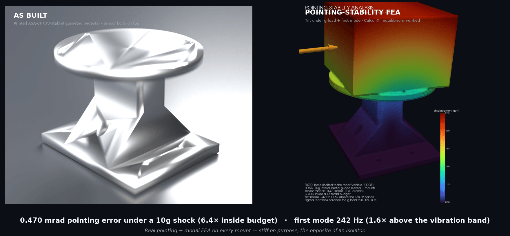
Σ reactions balance the g-load to 0.00% (the mesh validates itself), and the modal eigensolve is independently confirmed by a Rayleigh static-deflection frequency estimate to ~9%. The result: 0.470 mrad of pointing error under a 10g shock — 6.4× inside budget — and a first mode at 242 Hz, 1.6× above the vibration band. Stiff on purpose, and proven so.
How we engineered this: a mount that holds its aim under shock →

Specifications
| Pointing error under 10g | 0.470 mrad (1.61 arcmin) — 6.4× inside a ±3 mrad budget |
|---|---|
| First natural frequency | 242 Hz — 1.6× above a 150 Hz vibration band |
| Modal cross-check | Rayleigh static-deflection estimate agrees to ~9% |
| Sensor | ≈0.83 kg (Velodyne VLP-16) lumped (configurable mass + CG + standoff) |
| Configured envelope | 300–830 g sensor × 60–80 mm standoff off-the-shelf; heavier/taller = custom re-solve |
| Material | ASA-CF (UV-stable outdoor + carbon-fiber rigidity) |
| Mount | M5 base + Velodyne VLP-16 6× M3 on Ø103.3 mm bolt circle |
| Analysis | CalculiX C3D10 static + modal, equilibrium-verified |
Application and configuration notes
The sensor is carried as a lumped mass at its CG — exact pointing depends on your sensor's real mass and CG, which the configurator takes as inputs and re-solves. Pointing is the quasi-static tilt under the g-load; a full random-vibration PSD response is offered as the next step. For a precision optical payload, check the thermal environment. The FEA is the design; a tap-test and shaker pointing check on the as-built are the deliverable.
Configure to your part
Enter the envelope of the part you need to inspect. We auto-size the 3-2-1 fixture, then run the real FEA to confirm the datum holds before you pay.
Estimate only — every fixture is FEA-validated for datum stability and quoted before work begins.
In use
The part
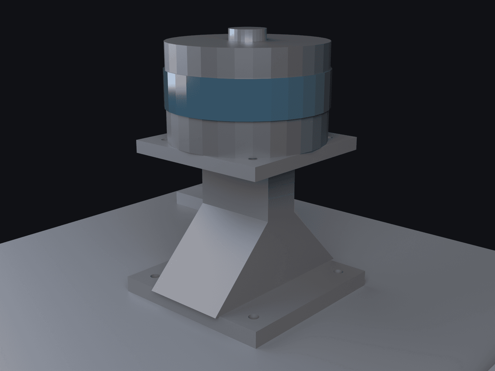
A rigid pedestal that holds a sensor — lidar, camera, antenna — clear of a robot or vehicle. Its whole job is to not move: under driving vibration and shock the sensor sees a g-load, and if the mount deflects or resonates, the boresight wanders and the data smears. A wobbling lidar on a survey vehicle means a corrupted point cloud and a re-drive.
So this is the inverse of a soft isolator — we want it stiff, and we prove two things about it. First, pointing: under a 10g lateral shock the sensor face tilts just 0.47 mrad, 6.4× inside an angular-resolution-class budget. Second, resonance: the mount's first natural frequency is 242 Hz, 1.6× above the top of a typical vehicle vibration band, so it never rings. Both come from finite-element analysis — a static g-load solve for the tilt and a modal solve for the frequency.
ASA-CF (carbon-fiber ASA), chosen as the engineering, not a default: a survey sensor lives outdoors on a vehicle or UAS, so the material has to be UV-stable — plain nylon isn't, and it's hygroscopic enough to drift a precision optical datum. ASA is the UV-stable outdoor polymer and, being amorphous, barely absorbs moisture; the carbon fiber gives back the stiffness this mount is sold on. The honest trade, stated up front: ASA-CF is a little less stiff than CF-Nylon, so the margins are tighter (still 6.4× on pointing, 1.6× on the first mode) — that reduction buys the UV and dimensional stability an outdoor sensor needs. The geometry is parametric on your sensor's mass, its centre-of-gravity height, and the standoff you need for field of view — so the mount configures to your sensor and re-solves both the pointing and the mode for that exact build.