Engineering Examples · Robotics & UAS hardware
A mount that holds its aim under shock
A lidar that wobbles under vehicle vibration smears its point cloud. We proved this mount holds the boresight to a third of a milliradian under a 10g shock — and never resonates.
The result at a glance
Problem → built result
What we solved
Mount a lidar or camera on a moving robot or vehicle and the sensor stops seeing a stable world. Driving vibration and shock load the mount, and if it deflects, the boresight tilts; if it resonates, the whole sensor rings. Either way the data smears — a survey lidar returns a fuzzy point cloud, and the operator re-drives the route.
What we built
Treat the mount as exactly what it is — a stiff pedestal carrying a tip mass — and design it to be the opposite of a vibration isolator. Where an isolator wants to be soft, a pointing mount wants to be stiff: low angular deflection under load, and a first mode safely above the excitation.

How we proved it
The engineering behind the result.
Pointing error, in milliradians
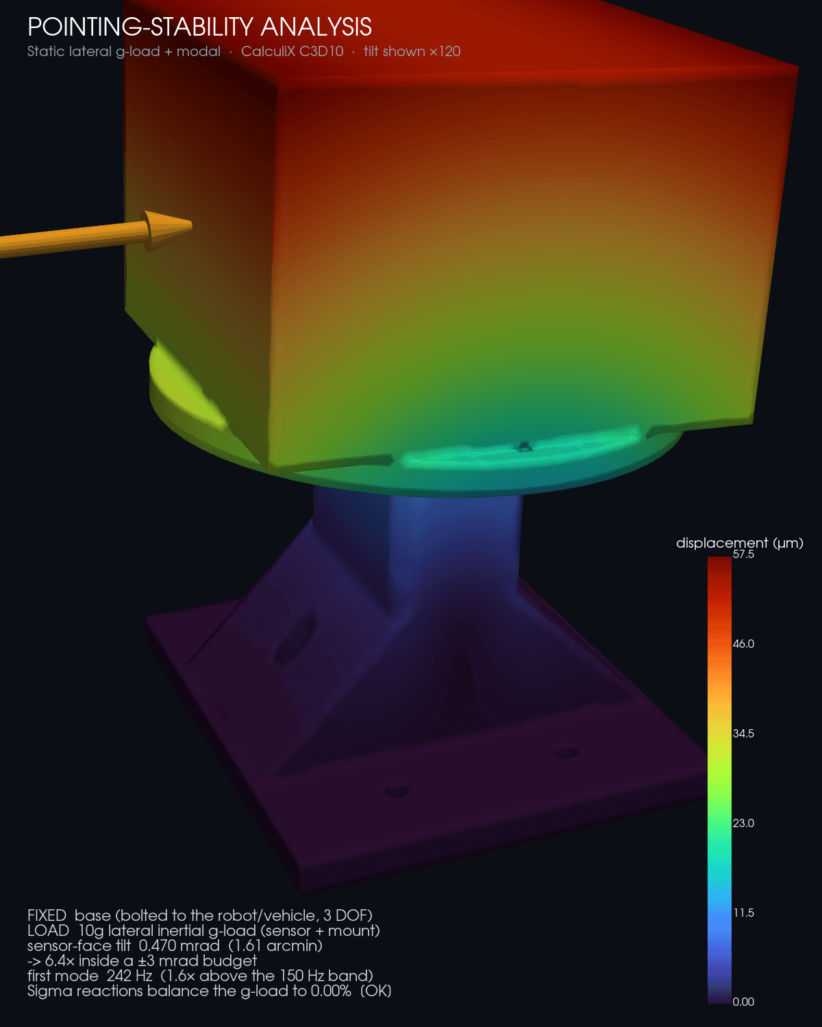
Under a 10g lateral shock the sensor mounting face tilts 0.47 mrad — about 1.6 arcminutes — which is 6.4 times inside an angular-resolution-class pointing budget.…
No resonance, with margin
The mount's first natural frequency is 242 Hz, 1.6× above the top of a typical vehicle vibration band, so it never rings at the frequencies the platform produces.…
Two independent checks before we quote a number
The static reactions balance the applied g-load to 0.00% — the mesh validating itself. And the modal eigensolve is confirmed by an independent static-deflection frequency estimate to within 8%, the modal equivalent of an equilibrium check.…
Delivered result
Evidence a buyer can use.
A sensor mount that ships sized to the customer's sensor, with the analysis proving it holds its aim under shock and stays clear of resonance — not a bracket that's 'probably stiff enough.' The honest gates travel with it: the sensor is a lumped mass (the configurator takes the real mass and CG), the pointing figure is the quasi-static tilt (a full random-vi…
Application notes
The sensor is carried as a lumped mass at its CG — exact pointing depends on the real sensor's mass and CG, which the configurator takes as inputs and re-solves. Pointing is the quasi-static tilt under the g-load; a full random-vibration PSD response (Miles' equation) is the offered manufacturing-grade step.…
Quote
Configure the Sensor / Camera / Lidar Mount.
Photos, a drawing, or dimensions. We’ll quote the job if we can take it.