Shop · Robotics & UAS Hardware
Commercial Drone Landing Gear
Sized to your aircraft, validated to the landing — the FoS is computed.
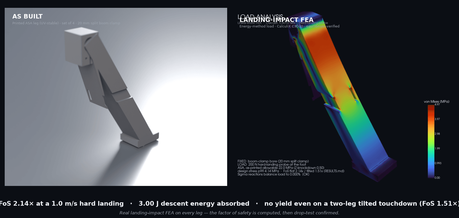
Σ reactions balance the landing load to 0.00% and an independent beam cross-check agrees to 23% — so the mesh is provably valid. At a 1.0 m/s hard landing the leg holds 2.14× inside the as-printed ASA allowable; a tilted touchdown that drops the energy onto two legs still holds 1.51× with no yield. The factor of safety is computed, then drop-test confirmed.
How we engineered this: sizing a leg to the landing, not the datasheet →
Specifications
| Factor of safety (rated landing) | 2.14× at a 1.0 m/s hard landing (full 6 kg AUW) |
|---|---|
| Worst-case landing | 1.51× on a tilted 2-leg touchdown — no yield |
| Static margin | 72× standing at rest |
| Energy absorbed | 3.0 J descent KE at the rated landing |
| Material | ASA (UV-stable); optional TPU skid foot; UV-stabilized PA variant |
| Mount | Split boom clamp for a 20 mm OD arm tube (configurable) |
| Set | 4 legs · 200 mm tall · 92 mm stance (sized to your AUW) |
| Analysis | CalculiX C3D10 FEA, energy-method load, equilibrium-verified |
Application and configuration notes
The rating is for a single hard landing; repeated hard landings are a fatigue duty — no fatigue knockdown is in this static-energy model, and we offer a cyclic-landing test (ASTM D7791). The 1.0 m/s rating's margin is spent by a 1.51 m/s two-leg slam, so for faster descents or higher AUW we re-size the strut. ASA is the outdoor/UV choice; for indoor max-toughness a UV-stabilized PA variant is offered. The FEA is the design; a measured drop test on the as-built is the deliverable.
In use
The part
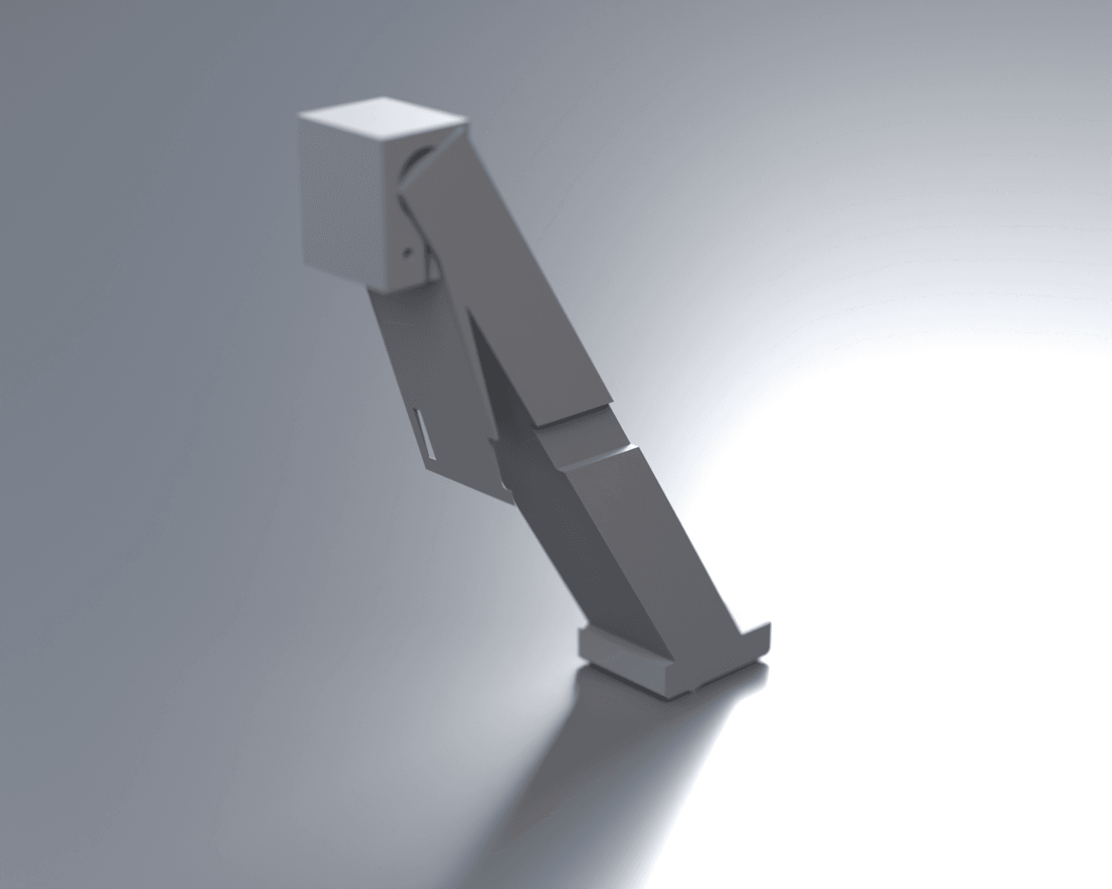
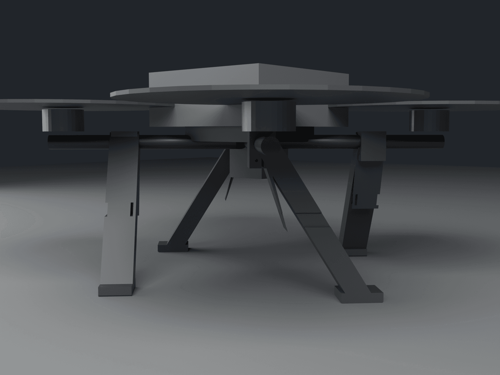
A cantilever skid landing-gear leg for a commercial multirotor — survey, inspection, mapping. A split boom clamp wraps a standard 20 mm OD arm tube, a tapered ribbed blade strut sweeps down and out, and a skid foot meets the ground. Sold as a set of four. On touchdown the leg flexes as a spring, trading the aircraft's descent energy for bending strain energy — that controlled flex is the whole job. The clamp grips the full tube circumference, so landing side- and yaw-loads react through the clamp, not a couple of bolts.
The hobby tier is a race to the bottom of free STLs and $5 imports; we don't play there. A commercial operator who cracks a leg on a hard landing eats a re-fly and risks a gimbal strike worth far more than the gear. So this isn't a generic skid — it's a leg sized to your all-up weight and descent spec, and it ships with the analysis. The headline factor of safety is the output of a finite-element analysis run on the exact part in its as-printed orientation, with the landing load derived by the energy method and an interlayer knockdown applied because the strut root bends across its print layers.
Material is the engineering, not a default: ASA, because landing gear lives outdoors in direct sun and ASA is the UV-stable engineering polymer — unstabilized nylon yellows and loses the very impact toughness this part needs under prolonged UV. The honest trade, stated up front: ASA's impact toughness is lower than nylon's, so the energy-absorption margin is tighter and we re-validate the FoS against the ASA allowable rather than assume it. For indoor-only flying where maximum toughness matters more than sun, a UV-stabilized / carbon-black PA is the configurable alternative; a TPU skid-foot overmold is offered for softer ground contact. The leg is parametric, so AUW, stance, strut section, and arm-tube OD configure to your aircraft and re-solve the FoS for that exact build.