Engineering Examples · Test, lab & inspection fixturing
Keeping 64 pins in contact under load
A bed-of-nails test fixture is only as good as its worst pin. We proved the pin plane stays flat under the full preload — so no pin throws a false open.
The result at a glance
Problem → built result
What we solved
A DUT/pogo fixture presses a circuit board onto an array of spring-loaded pins to test it. Each pin needs a minimum contact force to read a clean, low-resistance node. The catch: the pins all push back at once, and the summed spring force of a full field — here 96 N across 64 pins — tries to bow the plate they sit in.
What we built
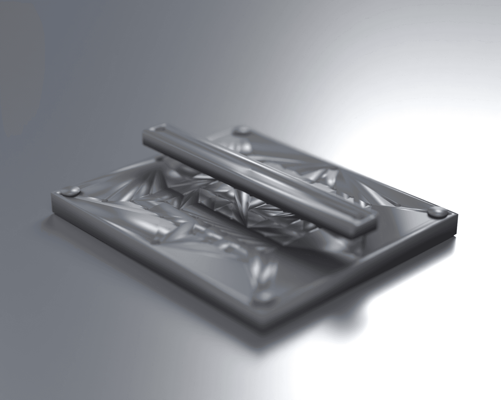
Treat the plate as a flat plate under a distributed load, because that's what it is. Pick the material for the one property that matters — rigidity — and compute the plate's deflection under the full pin preload, then convert that deflection straight into the thing the customer cares about: how much each pin's contact force varies across the field.
How we proved it
The engineering behind the result.
Flatness is the spec, not strength
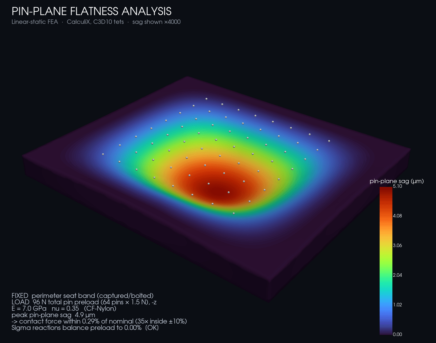
Under the 96 N preload the pin-base plane sags just 4.9 µm at its center. Through the pin spring rate, that 4.9 µm is a 0.3% change in contact force — 35× inside a ±10% uniformity target, so every pin stays in its reliable-contact band.…
CF-Nylon and steel, each where it belongs
The plate is carbon-fibre-filled nylon, chosen for stiffness and dimensional stability — the whole job is not moving under load. The pins ride pressed-in steel receptacles that take the contact and the wear.…
Bracketed by hand-calc, balanced to zero
The FEA flatness (4.9 µm) lands between two independent textbook plate-bending solutions — a clamped-edge plate (2.6 µm) and a simply-supported one (8.4 µm) — so the number isn't taken on faith from the solver.…
Delivered result
Evidence a buyer can use.
A printed test fixture that ships sized to the customer's board, with the analysis proving the pin plane stays flat enough that no pin throws a false open — backed by an FEA that's bracketed by hand-calc and balanced to zero.…
Application notes
The stiffness model uses the solid plate — the Ø1.2 mm pin holes (~1.4% of area on a 10 mm pitch) and the perimeter bolt/dowel holes are non-structural for plate bending and omitted. Flatness scales with pin count and plate span; the configurator re-solves each layout and we add a center support or step the thickness for a very large fiel…
Quote
Configure the DUT / Pogo Test Fixture.
Photos, a drawing, or dimensions. We’ll quote the job if we can take it.