Shop · Production Tooling, Jigs & Fixtures
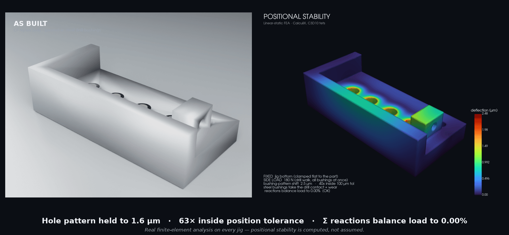
Both reaction components balance the applied loads to <1%, and the bushing pattern shifts 1.6 µm under the combined 180 N side + 480 N thrust — 63× inside a typical hole-position tolerance. The holes land where they should, and the analysis proves it under the real drilling load.
Specifications
| Positional stability | 1.6 µm pattern shift under combined 180 N side + 480 N axial thrust |
|---|---|
| Positional margin | 63× inside a 100 µm hole-position tolerance |
| Configurable | 2–8 holes, any pitch — each pattern FEA-validated |
| Locating / restraint | L-fence corner + integrated M6 push-clamp (3-2-1) |
| Material | CF-Nylon body, hardened-steel bushings |
| Bushings | DIN 179 form A press-fit, hardened 62 HRC (default Ø6 bore / Ø10 OD) |
| Analysis | CalculiX C3D10 FEA, equilibrium-verified |
Application and configuration notes
Sized to your hole pattern and drill size; the press into viscoelastic CF-Nylon relaxes, so the axial thrust is carried by the counterbored seat shoulder, not press friction alone. For high-volume production drilling or very tight true-position, we'll spec a DIN 172 flanged/adhesive-retained bushing or quote a hardened-plate hybrid.
Configure to your hole pattern
Enter your hole pattern and drill size. We auto-size the jig body, spec the pressed-in steel bushings, then run the real FEA to confirm the pattern holds under the drill side load before you pay.
Estimate only — every jig is FEA-validated for positional stability and quoted before work begins.
The part
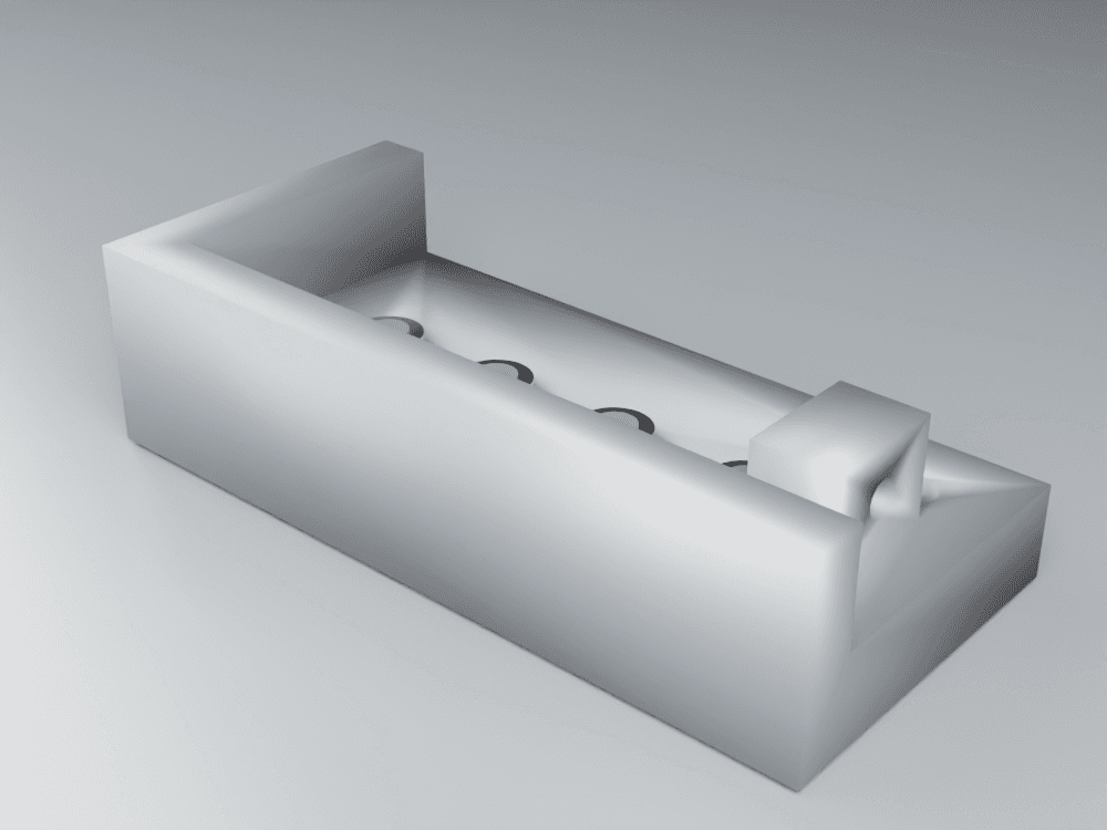
A drill jig guides your drill through a precise, repeatable hole pattern. The printed CF-Nylon body locates pressed-in hardened-steel drill bushings, and an L-fence registers the part corner — so every part gets the same holes in the same places.
The reason a printed jig works where you'd expect plastic to fail: the drill rides the steel bushing, never the body. Steel takes the contact, the bore precision, and the wear; the printed body only has to hold the pattern. That split is what lets a $40 printed jig replace a $300–1,500 machined one — overnight instead of weeks.
We don't assume the body holds the pattern, we compute it: every jig ships with the FEA showing the bushing centers stay put under the combined drilling load — 180 N of side walk and 480 N of axial thrust, every bushing pushed at once. An integrated M6 push-clamp drives the part into the L-fence (the active 3-2-1 restraint), and the axial thrust reacts into a counterbored retention shoulder under each bushing.
Configure it to your pattern below. The parametric template re-runs the full FEA on each layout; the default pattern holds the bushing centers to 1.6 µm under the combined side+thrust load — 63× inside a 100 µm position tolerance. So any pattern you configure is an individually-validated SKU, not a guess.